Ben North, May 2022
I've always liked the effect you get when two lights are flashing at not quite the same frequency. The pair of lights goes through intervals where they both flash on and off together, and intervals where one light is on when the other is off.
The right-hand light here is flashing about 5% more quickly than the left-hand light. If you watch it for half a minute or so, you can see the "flashing together" intervals and the "flashing opposite" intervals.
Once, I was behind several cyclists, and all their back lights were flashing, at slightly different frequencies. I wondered whether you could arrange a set of lights in a grid, each light flashing at a fixed frequency, such that every now and then they came into phase and made a picture which flashed, alternating with its "negative", as the small + sign to the left.
I played with this for a while, and realised you can make two pictures.
Suppose we're trying to make a pattern of flashing lights which repeats every minute. We'll use t to say how far through the minute we are, so t goes from 0 steadily up to 1 over the course of a minute, then instantly drops back to 0 again. We want to make one image appear at t = 0 and a different image appear at t = ½. How can we do this?
For the pattern to repeat after a minute, every light must do an integer number of on/off cycles in one minute. We'll first think about what happens for lights having different numbers of cycles fitting exactly into one minute.
A light which has 30 on/off cycles per minute, starting half-way through an "on" state, behaves like this:
This picture represents the light's behaviour on a big circular track. A pointer sweeps round anticlockwise, completing one revolution per minute, starting with t = 0 at the 3-o'clock position. At any instant, if it points at a black segment of the track, the light is off; if it points at an orange segment, the light is on.
We set things up so the light was on at the instant t = 0. It is also on at t = ½, because 30 is an even number.
If we wanted this light to be off at both t = 0 and t = ½, we could offset its phase by half a cycle:
Now we'll look at a light which does 29 on/off cycles per minute:
This light is on at t = 0 but off at t = ½, because 29 is an odd number.
If instead we want this light to be off at t = 0 and on at t = ½, we can offset its phase by half a cycle:
Putting this together, we can choose the behaviour of a light at both t = 0 and at t = ½.
Here, "frequency" means "(integer) number of cycles of that light per minute".
We can now think about a grid of lights, acting as pixels of an image. We want the grid to show one image at t = 0 and another image at t = ½. We can choose a 'centre' frequency, and then follow the above process to choose a frequency and phase for each light in the grid according to whether it should be lit or unlit at each of t = 0 (for the first image) and t = ½ (for the second image). We should choose different frequencies for each light (to make it interesting), and choose all the frequencies close to the centre frequency (so that the period when the lights are approximately in (anti-)phase is reasonably long). Each light's real-world frequency should be somewhere around 1Hz to look reasonable.
For many lights, we have to use a longer base time than "one minute" to get a reasonable result, but the ideas are all the same. There is a trade-off because we want the overall cycle to not be too long otherwise you hardly ever see the pictures.
The result is something which for a lot of the time looks like random flashing lights, but now and then coheres into one of two images flashing "positive and negative". For the small 3×3 example below, the two pictures are an "O" and an "X". In the triptych at the bottom, the circle-with-moving-bead in the middle shows where the pattern is in its global cycle. When the bead is at 3 o'clock (t = 0), the big picture looks like the right-hand small picture, flashing "positive and negative". When the bead is at 9 o'clock (t = ½), the big picture looks like the left-hand small picture, flashing "positive and negative".
You can click/tap on the small pictures to warp time directly to a few seconds before that picture comes into coherence.
Here's a bigger example, which takes three minutes to cycle:
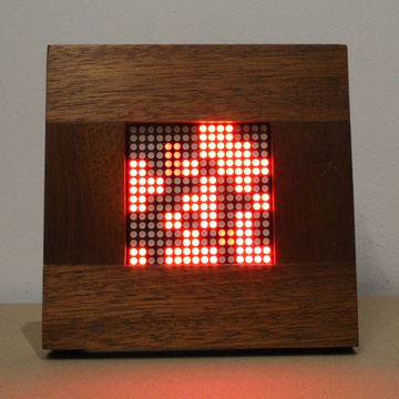
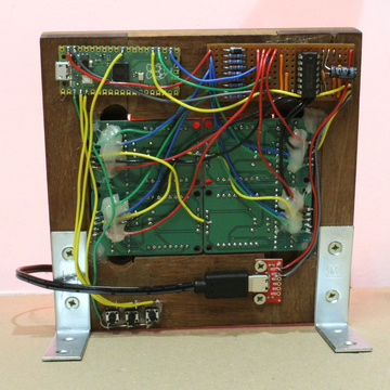
This is all well and good, but I really wanted actual physical flashing lights.
I built a display using four 8×8 LED matrices, glued together and then driven in a pixel-doubled way to keep the effective resolution as 8×8. I made the frame out of some mahogany (I think), which was going to be thrown out. The whole thing is held together with quite a lot of hot glue, and looks better from the front.
Controlling it is a Raspberry Pi Pico with a level-shifter/driver to interface with the displays. The software is in C++, and updates the display at about 100Hz, using a Bresenham-like algorithm to perform all calculations with integers. (The same idea is used for the JavaScript running the demos on this page.)
The source code for this page and the C++ code for the Pico is available on GitHub: